360 Image extension
Displays 360 cube-map images with optional multiple levels of details. Can also use corresponding depth-maps to position 360 image correctly in the scene and support picking.
Usage
Use Image360 entity to display 360 lod images.
Set full path of file 360.json in 360 image folder in field Image360Component.source.
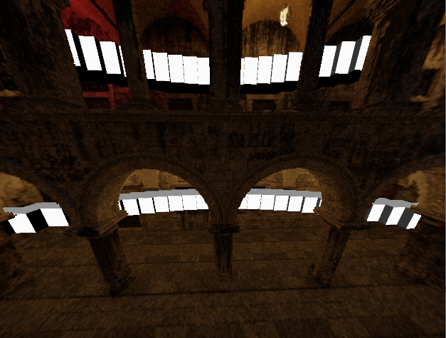
Sponza model converted to 360 image using Blender. Rendered in Cogs with Cogs Cubes.
NOTE that the rendering algorithm requires that the camera MUST be in center of the 360 image, e.g. position of point-cloud scanner if generated from point-cloud data.
If using Cogs OrbitingCameraController component for interaction set fields:
orbitingCameraController.moveCamera = false;
camera.transformComponent.coordinates = ScanPosition..;
Cogs Tools DepthMap can be used to generate 360 Images with DepthMaps from laser scans.
Cube map images can be used to create 360 lod images without depth. Check orientation of images using one level. Then partition into wanted lod.
Tuning display of 360 Images
Field Image360Component.subsampling is used to determine which LOD level to show.
Balance between loading a lot of data vs display quality.
Approximately how many pixels on screen should a 360 lod pixel cover.
Decrease towards 1 or lower for highest quality.
Subsampling here is the opposite of supersampling (which means to use more than one sample to generate one sample), so subsampling was intended to mean using less than one sample to generate one sample.
Also see 360 image specific variables image360.* in Variables Documentation
Depth maps
The depth stored in the depth maps are assumed to encode the distance from the eye to the point, and not distance along Z, which is what you typically get from a depth buffer.
The distance from eye can be found from a depth buffer value by multiplying the depth buffer value with the factor
1 / (cos(theta_i)cos(theta_j))
where i,j are pixel positions in a cube map face of size N_i x N_j and
theta_i = pi/2( (i + 0.5)/N_i - 0.5), i=0,...,N_i-1
theta_j = pi/2( (j + 0.5)/N_j - 0.5), j=0,...,N_j-1
Configuration json file
A configuration json file looks like:
{
"baseSize": 256,
"treeDepth": 7,
"depthChannel":1,
"extent": 100.0,
"noDataDepth": 1000,
"discardNoDepth": false,
"channels": [
{
"dataType": "SRGB8_PNG",
"prefix": "color"
},
{
"dataType": "U16_ZST",
"prefix": "depth",
"scale": 0.01,
"bias": 0.0,
}
]
}
where
baseSizeis the width and height of images in the pyramid. All images have the same size. This value is not required to be a power of two, but it is probably a good idea to use a power of two to minimize padding in gpu texture memory.treeDepthis the depth of the tree. A value of 1 means that only the six base images are present, a value of two implies one level in addition to the base levels, and so on. The max resolution is thusbaseSize << (treeDepth-1), so in the example above,256 << (6-1) = 16384.depthChannelis the index in the channel with depth data in the channels array. If omitted, it is assumed that there is no depth data.noDataDepthis the depth value that represents a "no-data" flag. Typical values are either0oruint16::max(65535), especially when used with"discardNoDepth": true. If"discardNoDepth": false,noDataDepthis usually set slightly beyond the farthest point to ensure a smooth composition with other objects in the scene.discardNoDepthdetermines whether pixels without depth information should be discarded when depth data is available.extentis the defined radius around the eye, used to calculate bounds.channelsa list of data channels, where each channel is described with a json object. There can be up to 256 channels, which channel to view is specified on the component.
The data channels have the following structure:
dataTypespecifies the underlying datatype as well as the tile encoding:SRGB8_PNG: SRGB encoded 8-bit color data, stored as png. Assumes the.pngsuffix.SRGBA8_PNG: SRGB encoded 8-bit color data with alpha, stored as png. Assumes the.pngsuffix. Pixels with alpha=0 is discarded. 'SRGB8_JPEG: JPEG SRGB encoded 8-bit color data. Assumes the.jpgsuffix. May give improved compression, but no Alpha. Be aware of possible quality problems due to JPEG encoding.U16: Unsigned 16-bit values, stored raw in little endian byte order. Assumes the.u16suffix. Stored encoded distance.U16_ZST: Unsigned 16-bit values, stored raw in little endian byte order and subsequently compressed using Facebood Zstandard compression. Assumes the.u16.zstsuffix.
prefixis the relative path to tile files. The prefix gets tile number and file type suffix added. In the example above,colorimplies that base tile for face 2 has the path color2.png and so on.scaleis the scale to apply to uint values to get actual depth. In the example above, the 0.01 implies centimeter precision.biasis an optional value that is added to depth values moving the effective range away from the eye.
Tile files layout
The tile files have the name <prefix><treepos><suffix> where prefix is the
prefix from the channel description, treepos is a string of numbers
specifying where in the tree this tile belong, and suffix is implied by the
channel datatype.
The treepos value is organized such that the first value is a number [0,5] indicating the cube map face, next number [0,3] indices the child of that face, and the number [0,3] after that indicates which child of the child and so on.
Cubemap layout
There are six cubemap faces where
- Face 0 covers +X face, u = -Z, v = +Y
- Face 1 covers -X face, u = +Z, v = +Y
- Face 2 covers +Y face, u = +X, v = -Z
- Face 3 covers -Y face, u = +X, v = +Z
- Face 4 covers +Z face, u = +X, v = +Y
- Face 5 covers -Z face, u = -X, v = +Y
Child layout
There are always four children, where
- Child 0 covers u=[0,1/2), v=[0,1/2)
- Child 1 covers u=[1/2,1), v=[0,1/2)
- Child 2 covers u=[0,1/2), v=[1/2,1)
- Child 3 covers u=[1/2,1), v=[1/2,1)
TODO
- Occupancy bitmap: As long as the six base levels are present, completely empty tiles can be omitted. This will currently be reported as an error, but the dynamic tree won't descend unless all data is available. An occupancy bitmap will tell describe where the tree is empty, avoiding redundant failing fetches.